

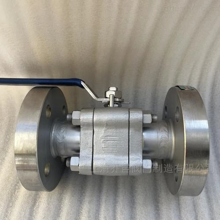


3-piece forged steel floating metal-seated ball valve brings together four specifications that each change how the valve is selected and used. The three-piece body is built from two end caps and a bolted center body that carries the ball and seats. The forged steel body is shaped from solid stock so the grain flow stays continuous and free of the porosity, sand inclusions and shrinkage that casting can introduce. The floating ball is not trunnion-mounted; it is pushed by line pressure against the downstream seat. The metal-seated closure seals by line contact between a hard-faced ball and a hard-faced seat ring, with no polymer or elastomer in the sealing path.
Together these traits target a service window that soft seats cannot occupy: sustained high temperature, abrasive or slurry media, and fire-risk lines. The three-piece construction then adds an advantage that two-piece metal-seated valves lack - the worn hard-faced sealing surfaces can be reached and renewed inline without unpiping the valve.
Design Standards
| Item | Standard |
|---|---|
| Basic Design | API 608/ASME B16.34/ISO 17292/API 6D |
| Face to Face/End to End | ASME B16.10 |
| Flanged End | ASME B16.5/MSS SP-44 ASME B16.47 |
| Buttwelding End | ASME B16.25 |
| Pressure-temperature Rating | ASME B16.34 |
| Inspection and Test | API 598 |
| Firesafe Design | API 607/API 6FA |
desgin features
1. Double sealing system of packing, and firesafe design
2. Wear-resistant and scour resistant sealing design
3. Integral anti-blowout design structure of the stem
4. Optional locking device
5. Independent limit structure design
6. Low torque design
7. Solid ball design
8. Ball and seat surface are coated with super wear-resistant alloy to ensure service life and sealing reliability.
9. Fugitive emission test meets API 624, ISO 15848 and other specifications.
Metal-to-Metal Seat Design
The closure is formed by precision-lapped line contact between a hard-faced ball and a hard-faced seat ring. Both faces carry a wear-resistant overlay, and the seat is deliberately softer than the ball so that any wear is taken by the renewable seat rather than the ball. A spring - usually an Inconel disc spring - sits behind the seat to keep contact through thermal expansion and low-pressure conditions.
Because there is no polymer in the sealing path, the valve is inherently tolerant of heat and fire: if a fire removes any auxiliary sealing, the metal-to-metal contact still closes the line. Body gaskets and stem packing use graphite so the valve remains seal-capable at temperature.
Floating Ball Action
In a floating design the ball is not carried on trunnion bearings. Upstream line pressure pushes the ball against the downstream seat, raising the contact load as pressure rises - a self-energizing action. In the standard arrangement the seal is therefore directional (loaded on the downstream side). Spring-energized seats can maintain sealing at low pressure and across thermal cycles, and in some arrangements support bidirectional closure. The distinction between floating and trunnion support is covered in the floating vs trunnion ball valve comparison.
Seat Leakage and Testing
Metal-to-metal sealing is intentionally not bubble-tight. The valve is tested and rated to ISO 5208 Rate D, which defines a small permitted leakage past the metal faces. Testing is performed per API 598, ISO 5208 or EN 12266-1. Typical production tests apply 1.5× the rated pressure on the shell and 1.1× on the seat. The comparison with soft seats is direct: a soft seat aims for bubble-tight closure (ISO 5208 Rate A), whereas a metal seat trades zero leakage for temperature, abrasion and fire survival.
General Assembly Drawing
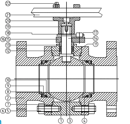
Material of Construction
| Part No. | Part Name | Carbon Steel | Stainless Steel |
|---|---|---|---|
| 1 | Body | ASTM A105N | ASTM A182 F316 |
| 2 | End Connector | ASTM A105N | ASTM A182 F316 |
| 3 | Ball | ASTM A105N+WC/HF/Ni60 | ASTM A182 F304/F316/F51+WC/HF/Ni60 |
| 4 | Seat | ASTM A105N+WC/HF/Ni55 | ASTM A182 F304/F316/F51+WC/HF/Ni55 |
| 5 | Nut | ASTM A194 2H | ASTM A194 8M |
| 6 | Stud | ASTM A193 B7 | ASTM A193 B8M CL2 |
| 7 | Gasket | SS304+Graphite | SS304+Graphite |
| 8 | Belleville Spring | Inconel-X750 | Inconel-X750 |
| 9 | Spring Holder | ASTM A182 F6a CL2 | ASTM A182 F316 |
| 10 | Firesafe Seal | Graphite | Graphite |
| 11 | Thrust Washer | SS304+Nitriding | SS304+Nitriding |
| 12 | Packing | Flexible Graphite | Flexible Graphite |
| 13 | Gland | ASTM A276 410 | ASTM A276 316 |
| 14 | Stem | ASTM A182 F6a CL2+Nitriding | ASTM A182 F316+Nitriding |
| 15 | Gland Flange | ASTM A105N | ASTM A182 F316 |
| 16 | Screw | ASTM A193 B7 | ASTM A193 B8M CL2 |
| 17 | Stop Plate | ASTM A240 410 | ASTM A240 304 |
| 18 | Retaining Ring | ASTM A29 1566 | ASTM A240 304 |
| 19 | Sleeve | ASTM A216 WCB | ASTM A216 WCB |
| 20 | Screw | ASTM A193 B7 | ASTM A193 B8M CL2 |
| 21 | Steel Pipe | ASTM A106+Zn | ASTM A106+Zn |
| 22 | Screw | ASTM A193 B7 | ASTM A193 B8M CL2 |
Note:
Floating metal seated ball valve can be designed as asymmetric structure according to customer requirements, with the same seat material and sealing surface on both sides.
Materials listed in the table are general. When ordering, please contact GNEE sales or technical team to confirm the details.
Dimension & Weight
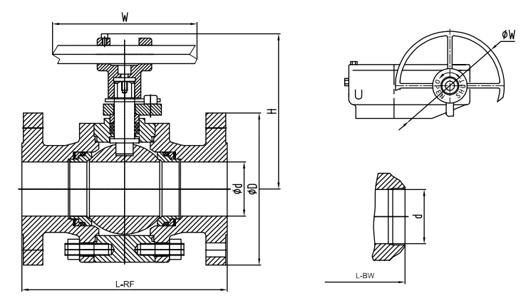
CLASS 150
| Size | L-RF | L-BW | d | D | H | W | Approx Weight | ||||||||
|---|---|---|---|---|---|---|---|---|---|---|---|---|---|---|---|
| NPS | DN | in | mm | in | mm | in | mm | in | mm | in | mm | in | mm | lb | kg |
| 1 | 25 | 5.00 | 127 | 6.50 | 165 | 0.98 | 25 | 4.33 | 110 | 4.33 | 110 | 10.24 | 260 | 13 | 6 |
| 1½ | 40 | 6.50 | 165 | 7.48 | 190 | 1.50 | 38 | 4.92 | 125 | 6.30 | 160 | 12.99 | 330 | 26 | 12 |
| 2 | 50 | 7.01 | 178 | 8.50 | 216 | 1.97 | 50 | 5.91 | 150 | 6.69 | 170 | 12.99 | 330 | 33 | 15 |
| 3 | 80 | 7.99 | 203 | 11.10 | 282 | 2.99 | 76 | 7.48 | 190 | 7.48 | 190 | 15.75 | 400 | 49 | 22 |
| 4 | 100 | 9.02 | 229 | 12.01 | 305 | 3.94 | 100 | 9.06 | 230 | 8.82 | 224 | 15.75 | 400 | 101 | 46 |
| 6 | 150 | 15.51 | 394 | 17.99 | 457 | 5.91 | 150 | 11.02 | 280 | 10.24 | 260 | 19.69 | 500 | 243 | 110 |
| 8 | 200 | 17.99 | 457 | 20.51 | 521 | 7.91 | 201 | 13.58 | 345 | 12.60 | 320 | 23.62 | 600 | 386 | 175 |
CLASS 300
| Size | L-RF | L-BW | d | D | H | W | Approx Weight | ||||||||
|---|---|---|---|---|---|---|---|---|---|---|---|---|---|---|---|
| NPS | DN | in | mm | in | mm | in | mm | in | mm | in | mm | in | mm | lb | kg |
| 1 | 25 | 6.50 | 165 | 6.50 | 165 | 0.98 | 25 | 4.92 | 125 | 4.72 | 120 | 9.84 | 250 | 22 | 10 |
| 1½ | 40 | 7.48 | 190 | 7.48 | 190 | 1.50 | 38 | 6.10 | 155 | 6.30 | 160 | 12.99 | 330 | 40 | 18 |
| 2 | 50 | 8.50 | 216 | 8.50 | 216 | 1.97 | 50 | 6.50 | 165 | 6.73 | 171 | 12.99 | 330 | 49 | 22 |
| 3 | 80 | 11.14 | 283 | 11.14 | 283 | 2.99 | 76 | 8.27 | 210 | 7.48 | 190 | 15.75 | 400 | 84 | 38 |
| 4 | 100 | 12.01 | 305 | 12.01 | 305 | 3.94 | 100 | 10.04 | 255 | 8.82 | 224 | 15.75 | #305 | 172 | 78 |
| 6 | 150 | 15.87 | 403 | 17.99 | 457 | 5.91 | 150 | 12.60 | 320 | 10.24 | 260 | 23.62 | #305 | 331 | 150 |
CLASS 600
| Size | L-RF | L-BW | d | D | H | W | Approx Weight | ||||||||
|---|---|---|---|---|---|---|---|---|---|---|---|---|---|---|---|
| NPS | DN | in | mm | in | mm | in | mm | in | mm | in | mm | in | mm | lb | kg |
| 1 | 25 | 8.50 | 216 | 8.50 | 216 | 0.98 | 25 | 4.92 | 125 | 5.39 | 137 | 12.99 | 330 | 22 | 10 |
| 1½ | 40 | 9.49 | 241 | 9.49 | 241 | 1.50 | 38 | 6.10 | 155 | 5.91 | 150 | 12.99 | 330 | 40 | 18 |
| 2 | 50 | 11.50 | 292 | 11.61 | 292 | 1.97 | 50 | 6.50 | 165 | 6.89 | 175 | 12.01 | #305 | 49 | 22 |
| 3 | 80 | 14.02 | 356 | 14.13 | 359 | 2.99 | 76 | 8.27 | 210 | 8.19 | 208 | 12.01 | #305 | 88 | 40 |
| 4 | 100 | 17.01 | 432 | 17.01 | 432 | 3.94 | 100 | 10.83 | 275 | 10.00 | 254 | 12.01 | #305 | 176 | 80 |
CLASS 900
| Size | L-RF | L-BW | d | D | H | W | Approx Weight | ||||||||
|---|---|---|---|---|---|---|---|---|---|---|---|---|---|---|---|
| NPS | DN | in | mm | in | mm | in | mm | in | mm | in | mm | in | mm | lb | kg |
| 3/4 | 20 | 9.02 | 229 | 9.02 | 229 | 0.75 | 19 | 5.12 | 130 | 4.33 | 110 | 10.83 | 275 | 31 | 14 |
| 1 | 25 | 10.00 | 254 | 10.00 | 254 | 0.98 | 25 | 5.91 | 150 | 4.72 | 120 | 11.81 | 300 | 37 | 17 |
| 1½ | 40 | 12.01 | 305 | 12.01 | 305 | 1.50 | 38 | 7.09 | 180 | 5.51 | 140 | 13.78 | 350 | 62 | 28 |
| 2 | 50 | 14.49 | 368 | 14.61 | 371 | 1.97 | 50 | 8.46 | 215 | 6.89 | 175 | 15.75 | #400 | 88 | 40 |
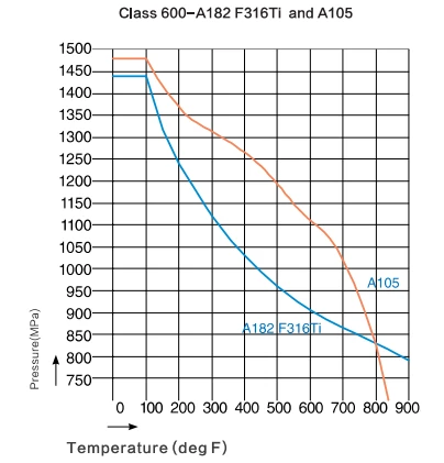
Pressure and Temperature Ratings for Floating Ball Valbe
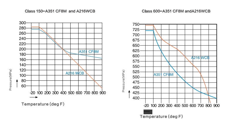
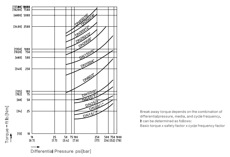
Break Away Torques for Floating Ball Valve
Basic Torque vs Differential Pressure
Medium Factor
| Medium | Safety Factors |
|---|---|
| Pure oil | 1.0 |
| Heat oil | 1.3 |
| Other hydrocarbons | 1.5 |
| water | 1.5 |
| Suspension, Slurry | 2.6 |
| Steam, Steam | 2.6 |
| Gas | 2.6 |
| Solid Particles | 3.0 |
Cycle Frequency Factor
| If a Valve is Cycled Once Per | Cycle Frequency Factor |
|---|---|
| Day or more | 1.25 |
| Week or more | 1.28 |
| Month or more | 1.30 |
| Every four month | 1.41 |
| Every eight month | 1.45 |
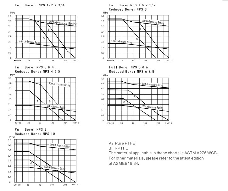
Pressure-Temperature Rating
Product Performance
| Performance Specifications | Nominal Pressure (MPa) | Pressure Rating (CLASS) | ||||||||
|---|---|---|---|---|---|---|---|---|---|---|
| 1.6 | 2.5 | 4.0 | 6.3 | 10.0 | 150 | 300 | 400 | 600 | ||
| Test Pressure (MPa) | Strength Test | 2.4 | 3.75 | 6.0 | 9.6 | 15.0 | 2.93 | 7.58 | 10.0 | 15.0 |
| Sealing Test | 1.76 | 2.75 | 4.4 | 7.04 | 11.0 | 2.07 | 5.52 | 7.31 | 11.03 | |
| Pneumatic Test | 0.6 | |||||||||
| Applicable Temperature | -196℃~300℃ (Note: Different materials shall be selected for different temperatures of services.) | |||||||||
| Applicable Medium | General | Water, steam, petroleum, liquefied gas, natural gas, etc. | ||||||||
| Anti-sulfur | Natural gas, oil, etc. , which contains H2S and CO. | |||||||||
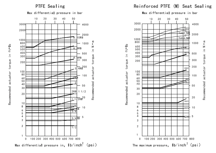
Reference Torques
Torque values listed in the chart below are for reference when selecting an actuator, All these values are under full differen-tial pressure,for the medium
type,trim,opening frequency of the valve should be further considered.For critical medium,such as slurry,particulate and oxygen,these torque valves need to be multiplied by a safety factor of 1.5 times. Operation torque of reduced port valve shoud be selected as per the reduced port torque value.
Torque Chart
Torque Value (N·m)
Full Port (mm)
| Pressure | 15 | 20 | 25 | 40 | 50 | 65 | 80 | 100 | 125 | 150 | 200 |
|---|---|---|---|---|---|---|---|---|---|---|---|
| PN1.6 MPa | 3 | 5 | 10 | 16 | 25 | 50 | 65 | 125 | 250 | 340 | 485 |
| PN2.5 MPa | 3 | 5 | 11 | 18 | 30 | 60 | 80 | 140 | 300 | 400 | 680 |
| PN4.0 MPa | 5 | 10 | 24 | 35 | 50 | 100 | 150 | 250 | 450 | 585 | 996 |
| PN6.4 MPa | 15 | 30 | 50 | 80 | 100 | 200 | 300 | 400 | – | – | – |
| PN10.0 MPa | 19 | 35 | 68 | 130 | 190 | 360 | 460 | 770 | – | – | – |
Note: Data listed in the table are not measured and for reference only.
Full Port (in)
| Pressure | 1/2 | 3/4 | 1 | 1½ | 2 | 2½ | 3 | 4 | 5 | 6 | 8 |
|---|---|---|---|---|---|---|---|---|---|---|---|
| Class 150 | 3 | 5 | 11 | 16 | 25 | 50 | 65 | 125 | 250 | 410 | 700 |
| Class 300 | 7 | 12 | 26 | 38 | 60 | 120 | 160 | 280 | 600 | 950 | 1550 |
| Class 400 | 15 | 30 | 50 | 90 | 140 | 240 | 350 | 540 | – | – | – |
| Class 600 | 19 | 35 | 68 | 130 | 190 | 360 | 460 | 770 | – | – | – |
Note: Data listed in the table are not measured and for reference only.
Note: Due to quick development of products, the data in our catalogue may be updated. GNEE reserves the right to change the design, material or specifications without prior notice and free of obligation to furnish or install such changes on products previously sold.
Typical Severe-Service Applications
High-temperature steam - superheated and saturated steam lines, boiler blowdown and drain.
Thermal oil - heat-transfer-fluid loops where soft seats would soften or degrade.
Abrasive slurries and mining - catalyst lines, fly ash, sand-laden and mineral slurries.
Fire-risk service - inherently fire-safe because no polymer is in the sealing path.
Hydrocarbon and process lines - where contamination from elastomer or PTFE seats is unacceptable.
Inspection, Certification and Sour Service
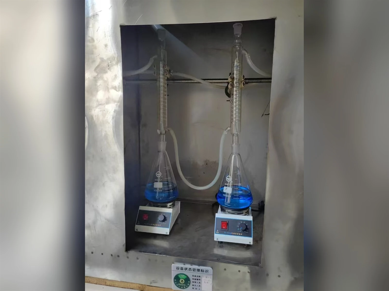
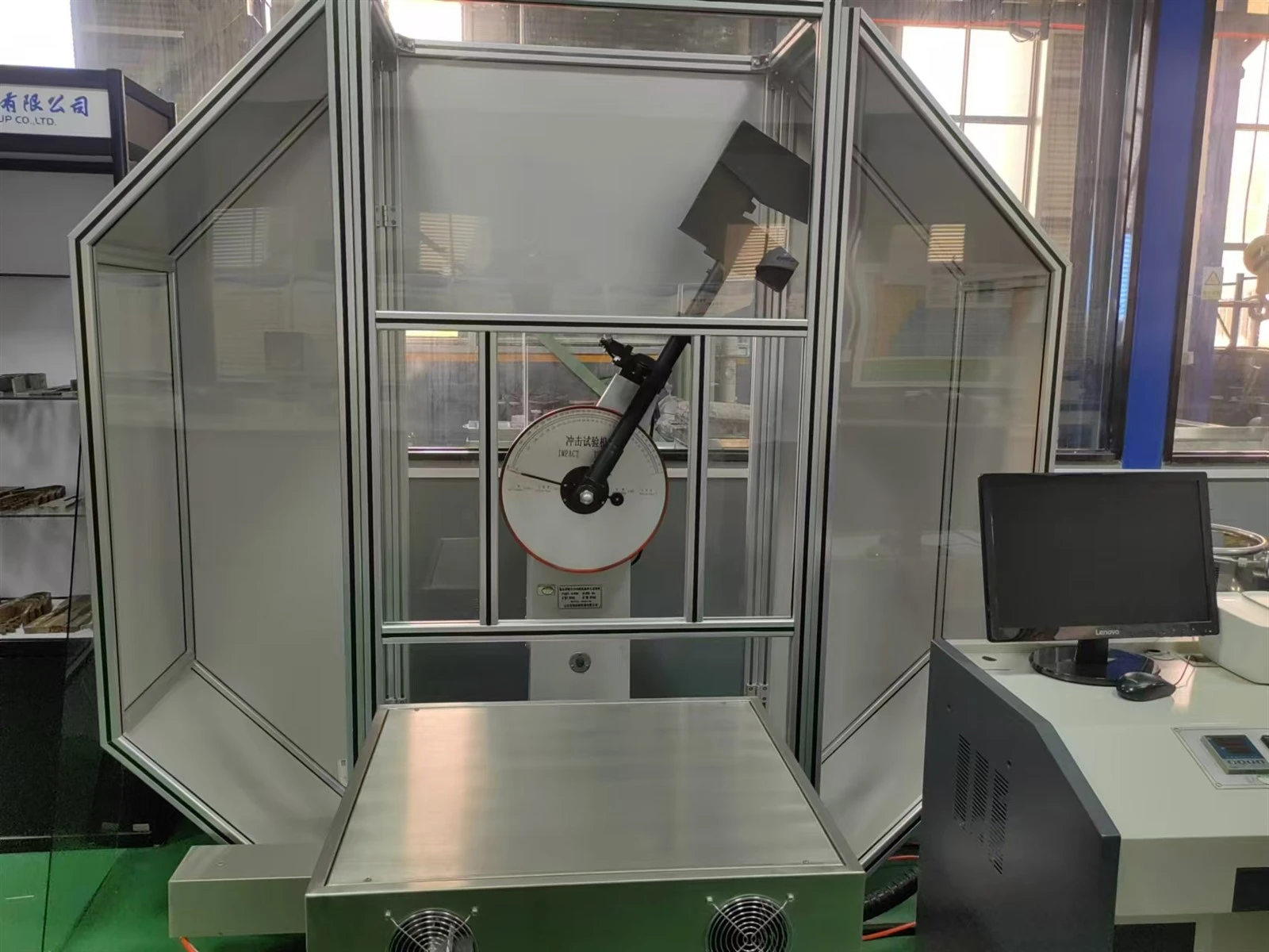
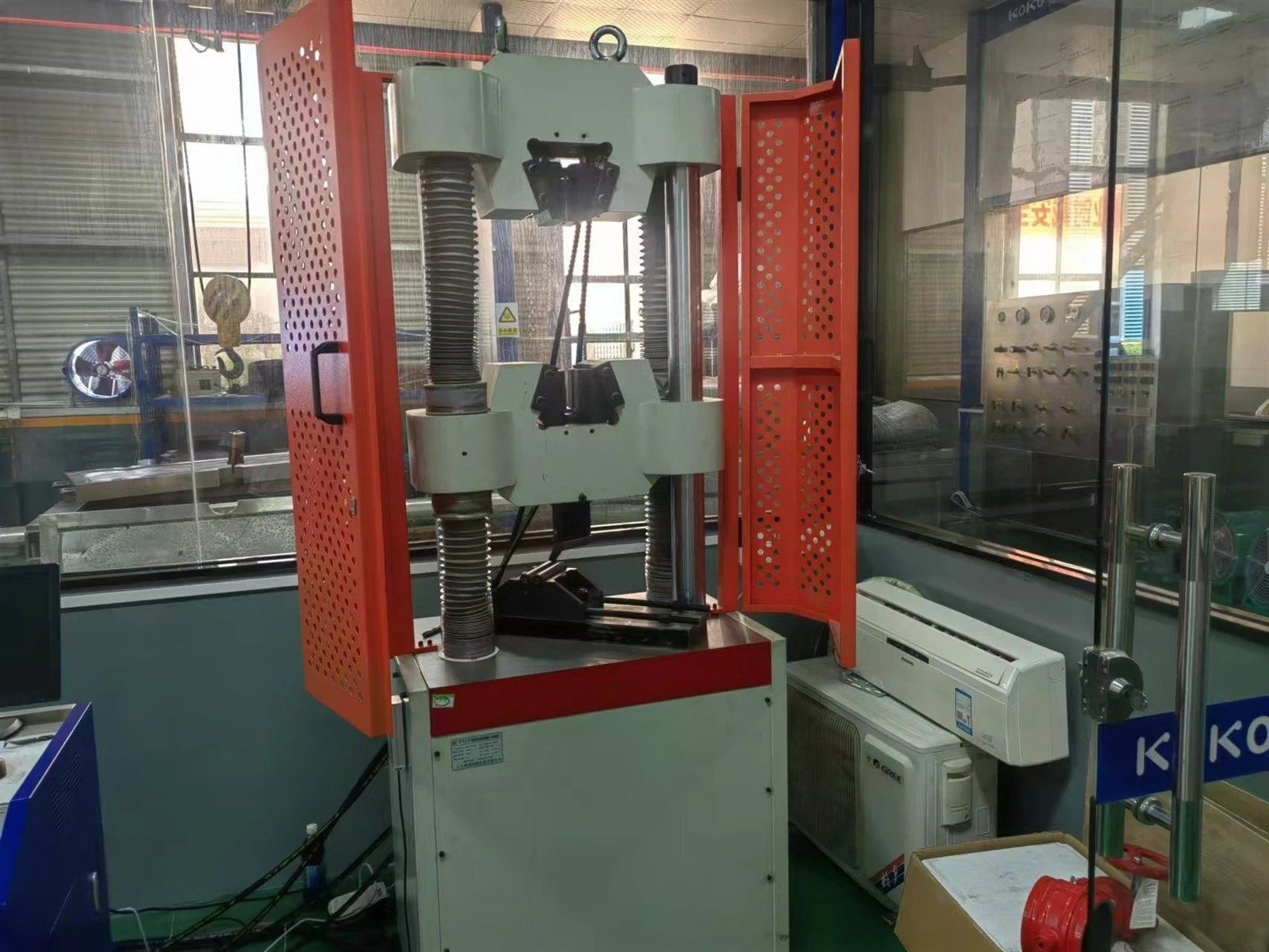
Standard safety features include a blow-out-proof stem, an anti-static path between ball, stem and body (per API 608), and an ISO 5211 actuator mounting pad. Fire safety is verified to API 607 / ISO 10497. Fugitive-emission packing to ISO 15848 is available on request. Sour-service configurations can be supplied to NACE MR0175 / ISO 15156 subject to material, heat-treatment and hardness controls, and material test certificates to EN 10204 3.1 or 3.2 are available.
FAQ
What is a 3-piece forged steel floating metal-seated ball valve?
It is a quarter-turn isolation valve that combines four traits: a three-piece forged body (two end caps plus a bolted center body), a floating ball that is loaded against the downstream seat by line pressure, and metal-to-metal sealing where both the ball and the seat rings are hard-faced and lapped. The forged body gives continuous grain flow and freedom from casting defects, while the metal seat lets the valve serve high-temperature, abrasive and fire-risk lines that soft seats cannot.
How does the three-piece body help maintain the metal seat inline?
In a three-piece design the ball and the hard-faced seat rings sit inside the center body cartridge. Loosening the body bolts lets the cartridge be pulled axially out of the line while the two end caps stay connected to the piping. Because metal seats wear and need periodic re-lapping or renewal, this lets a technician restore the sealing faces on site without cutting welded ends or lifting the whole valve out. A two-piece metal-seated valve offers no such cartridge pull-out and typically requires workshop removal.
What does "metal-seated" mean, and why is the seat not bubble-tight?
Metal-seated means the closure is formed by line contact between a hard-faced ball and a hard-faced seat ring, with no polymer or elastomer in the sealing path. The seat is not bubble-tight; it seals to ISO 5208 Rate D, which permits a small, defined leakage past the metal faces. That trade-off is accepted because metal seats survive temperatures, abrasion and fire that would destroy a soft seat. Seat leakage is verified per API 598, ISO 5208 or EN 12266-1.
Which hard-facing materials are applied to the ball and seat?
Common hard facings are cobalt-based Stellite 6, 12 or 21, tungsten carbide (WC-Co), chromium carbide (Cr3C2-NiCr), nickel-based Ni60 and hard chrome. Selection depends on service: tungsten carbide for severe abrasion and slurry, Stellite 6 or chromium carbide for high-temperature steam and thermal oil, and corrosion-resistant overlays for sour or chloride media. The ball and seat are deliberately made of dissimilar materials so any wear occurs on the renewable seat rather than the ball.
What temperature and service limits apply to the metal seat?
Indicative metal-seat limits run from about -29 °C up to roughly 538 °C, with chromium-carbide overlays extending capability toward higher temperatures. The actual limit is governed by the hard-facing choice, the body material pressure-temperature rating per ASME B16.34, and the pressure and medium. Metal seats are selected for high-temperature steam, thermal oil, abrasive slurries, mining and fire-risk service rather than for clean cryogenic or bubble-tight duties.
What body and trim materials are used, including seat hard-facing?
The forged body and end caps use ASTM A105 or A105N carbon steel, A350 LF2 for low temperature, A182 F304/F316/F316L stainless, and A182 F11/F22 chrome-moly alloy. The ball and stem are typically A182 stainless or alloy grades with a hard-faced overlay. The seat rings are stainless or alloy substrates carrying Stellite, tungsten carbide or chromium-carbide hard facing, often spring-energized by an Inconel disc spring.
Which standards and pressure classes apply to this valve?
Design and manufacture follow API 608 (primary), ASME B16.34 for pressure-temperature ratings, ISO 17292 and BS 5351, with API 6D available for pipeline service. Face-to-face dimensions follow ASME B16.10. Ends may be NPT (ASME B1.20.1), socket weld (ASME B16.11), butt weld (ASME B16.25) or flanged (ASME B16.5/B16.47). Typical forged three-piece sizes are NPS 1/4-2 (DN8-50) at Class 150-1500; the floating type is generally applied within NPS 8 (DN200) and Class 600, with larger or higher-pressure cases evaluated as trunnion.
What information is needed to request a quotation?
Provide the nominal size and pressure class, end connection type, required body and trim materials, the process medium, operating and design temperature and pressure, any abrasive or sour-service condition (NACE MR0175/ISO 15156 if applicable), the desired seat hard-facing, and the testing and certification level such as EN 10204 3.1 or 3.2. These inputs let the supplier confirm the forged three-piece metal-seated configuration and the applicable leakage class.
Hot Tags: 3-pc forged steel floating metal seated ball valve, China 3-pc forged steel floating metal seated ball valve manufacturers, suppliers, factory, ball valve after sales service, ball valve delivery, ball valve diaphragm actuators, ball valve manufacturers, ball valve marking, three piece ball valve