

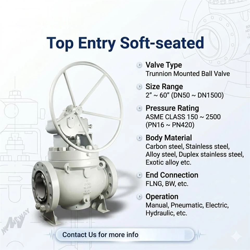


The top entry trunnion mounted soft seated ball valve is a quarter-turn isolation product for transmission pipelines, terminals and process systems where the valve must both hold high differential pressure and be serviced in place. Its distinction is the body architecture: a single-piece (unibody) body carries the pipe connections, and a bolted top cover closes the only main opening. All of the working parts - ball, trunnions, bearings and seats - are installed and withdrawn through that top opening.
Compared with a side-entry two-piece or three-piece valve, the top entry body has fewer external bolted joints, so it has the fewest potential leak paths and a shorter, more compact face-to-face for a given bore. Compared with a floating valve, the trunnion support holds the ball against line thrust and gives bidirectional sealing with low, stable torque. The following sections explain the working principle, the inline service method, the body comparison, seat and material options, isolation arrangements, dimensions, standards, testing and the information needed for a quotation.
How a Top Entry Trunnion Ball Valve Works
In a trunnion mounted valve the ball carries integral upper and lower trunnion shafts that ride in bearings, so the ball is held at the centre of the cavity and cannot shift laterally under line pressure. In a top entry valve the upper trunnion bearing is housed in the top cover and the lower trunnion bearing in the body, which is why the ball and trunnion assembly can be lifted out once the cover is removed. Line thrust is taken through the trunnions and bearings into the body, not through the seats.
The two seats are annular assemblies backed by disc or wave springs. At low pressure the springs provide the initial sealing force; as line pressure rises it adds a self-energising force behind each seat, pressing the seat against the stationary ball. Because the seats carry only the contact stress needed to seal, seat loading stays roughly constant and operating torque does not climb with pressure.
With both seats independently loaded, the valve seals against pressure from either direction. This is the basis of its bidirectional capability and of the double block and bleed (DBB) or double isolation and bleed (DIB) function described below.
Top Cover and Inline Service
The operational value of the top entry design is that maintenance happens from the top of the valve. The body is welded or bolted into the pipeline and stays there; the top cover is unbolted and lifted off, and the ball, trunnions, bearings and seat cartridges are withdrawn through the top opening for cleaning, inspection or replacement. The pipe run is not cut, drained or re-aligned, so the work avoids a full line shutdown and the re-qualification of field welds.
That method suits installations where access is difficult. A buried or underground mainline valve can be reached through a stem extension and a small pit without excavating the whole body, and a valve in a compact or congested skid can be serviced without moving adjacent equipment. Dedicated tooling is normally used to lift the internals, and the top cover joint is re-made to the bolting and gasket requirements of the governing standard. Where a valve is expected to be opened regularly, the seat and seal design is selected so the cartridges can be replaced as sets.
Design Standards
| Item | Standard |
|---|---|
| Basic Design | API 6D/ASME B16.34 |
| Face to Face/End to End Dimension | ASME B16.10/API 6D/SNY Standard |
| Flanged End Dimension | ASME B16.5/ASME B16.47 |
| Buttwelding End Dimension | ASME B 16.25 |
| Pressure-temperature Rating | ASME B16.34 |
| Inspection and Test | API 6D |
| Firesafe | API 607/API 6FA |
design features
1. Double sealing system of packing, and firesafe design
2. Stem with emergency grease injection
3. Integral anti-blowout design structure of the stem
4. Floating preload seat ring design to ensure good sealing under low pressure
5. Double block and bleed function (DBB)
6. Double isolation and bleed function (DIB)
7. Anti-static function
8. Low torque design
9. Top flange self-limited design
Top Entry Trunnion Mounted Soft Seated Ball Valve drawing
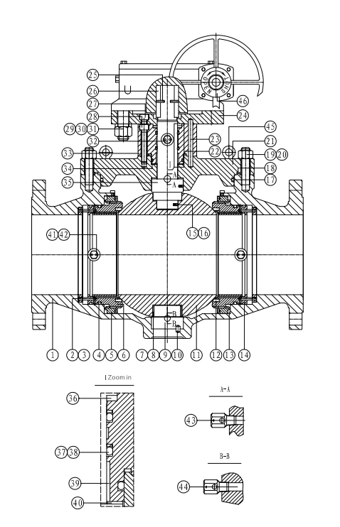
Material of Construction
| Part No. | Part Name | Carbon Steel | Low Temperature | Stainless Steel |
|---|---|---|---|---|
| 1 | Body | ASTM A216 WCB | ASTM A352 LCB/LCC | ASTM A351 CF8/CF8M |
| 2 | Anti-rotate Sleeve | ASTM A276 Type 410 | ASTM A350 LF2 | ASTM A182 F304/F316 |
| 3 | Pin | ASTM A29 1566 | ASTM A276 304 | ASTM A276 304 |
| 4 | O-ring | NBR/HNBR/VITON | NBR/HNBR/VITON | NBR/HNBR/VITON |
| 5 | Spring Seat | Carbon Steel | A350 LF2+ENP | ASTM A182 F304/F316 |
| 6 | Seat Ring | ASTM A105N+ENP | A350 LF2+ENP | ASTM A182 F304/F316 |
| 7 | Thrust Washer | ASTM A29 1045+PTFE | SS304+PTFE | SS304/SS316+PTFE |
| 8 | Bearing | ASTM A29 1045+PTFE | SS304+PTFE | SS304/SS316+PTFE |
| 9 | Trunnion | ASTM A105N+ENP | ASTM A350 LF2+ENP | ASTM A182 F304/F316 |
| 10 | Pin | ASTM A29 1566 | ASTM A276 304 | ASTM A276 304 |
| 11 | Ball | ASTM A105N+ENP | ASTM A350 LF2+ENP | ASTM A182 F304/F316 |
| 12 | Seat Insert | RTFE/NYLON/DEVLON | RTFE/NYLON/DEVLON | RTFE/NYLON/DEVLON |
| 13 | Spring | INCONEL X-750 | INCONEL X-750 | INCONEL X-750 |
| 14 | O Ring | NBR/HNBR/VITON | NBR/HNBR/VITON | NBR/HNBR/VITON |
| 15 | Spring | SS304 | SS304 | SS304 |
| 16 | Ball | SS304 | SS304 | SS304 |
| 17 | O-ring | NBR/HNBR/VITON | NBR/HNBR/VITON | NBR/HNBR/VITON |
| 18 | Gasket | SS304+Graphite | SS304+Graphite | SS304/SS316+Graphite |
| 19 | Nut | ASTM A194 2HM | ASTM A194 7M | ASTM A194 8M |
| 20 | Stud | ASTM A193 B7M | ASTM A320 L7M | ASTM A193 B7M |
| 21 | Bonnet | ASTM A216 WCB | ASTM A352 LCB/LCC | ASTM A351 CF8/CF8M |
| 22 | Gasket | SS304 + Graphite | SS304 + Graphite | SS304 + Graphite |
| 23 | Pin | ASTM A29 1566 | ASTM A276 304 | ASTM A276 304 |
| 24 | Top Flange | ASTM A105N | ASTM A350 LF2 | ASTM A182 F304/F316 |
| 25 | Pin | ASTM A29 1566 | ASTM A276 304 | ASTM A276 304 |
| 26 | Key | ASTM A29 1045 | ASTM A240 304 | ASTM A240 304 |
| 27 | Screw | ASTM A193 B7M | ASTM A320 L7M | ASTM A193 B7M |
| 28 | Screw | ASTM A193 B7M | ASTM A320 L7M | ASTM A193 B8M |
| 29 | Nut | ASTM A194 2HM | ASTM A194 7M | ASTM A194 8M |
| 30 | Stud | ASTM A193 B7M | ASTM A320 L7M | ASTM A193 B8M |
| 31 | Washer | ASTM A29 1566 | ASTM A276 304 | ASTM A276 304 |
| 32 | Sealant Injection | SS304 | SS304 | SS304 |
| 33 | Bonnet Cover | ASTM A29 4140/A105N+ENP | ASTM A350 LF2+ENP | ASTM A182 F304/F316 |
| 34 | O-ring | NBR/HNBR/VITON | NBR/HNBR/VITON | NBR/HNBR/VITON |
| 35 | Stem | ASTM A29 4140/A105N+ENP | ASTM A29 4140/A350 LF2+ENP | ASTM A182 F304/F316 |
| 36 | Gasket | Graphite | Graphite | Graphite |
| 37 | O-ring | NBR/HNBR/VITON | NBR/HNBR/VITON | NBR/HNBR/VITON |
| 38 | Retaining Ring | PTFE | PTFE | PTFE |
| 39 | Thrust Washer | ASTM A29 1045+PTFE | SS304+PTFE | SS304/SS316+PTFE |
| 40 | Bearing | ASTM A29 1045+PTFE | SS304+PTFE | SS304/SS316+PTFE |
| 41 | Check Valve | SS304 | SS304 | SS304/SS316 |
| 42 | Sealant Injection | SS304 | SS304 | SS304/SS316 |
| 43 | Vent Valve | SS304 | SS304 | SS304/SS316 |
| 44 | Drain Valve | SS304 | SS304 | SS304/SS316 |
| 45 | Lifting Eye | SS304 | SS304 | SS304/SS316 |
| 46 | Gearbox | Carbon Steel | Carbon Steel | Carbon Steel |
Note: Materials listed in the table are general. When ordering, please contact GNEE sales or technical team to confirm details.
Dimension & Weight
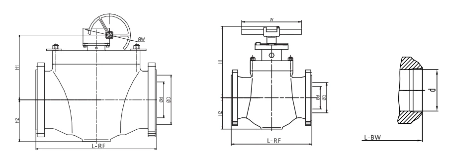
CLASS 600 Full Bore
| NPS | DN | d(in) | d(mm) | L-RF(in) | L-RF(mm) | L-BW(in) | L-BW(mm) | H1(in) | H1(mm) | H2(in) | H2(mm) | W(in) | W(mm) | Approx Weight(lb) | Approx Weight(kg) |
|---|---|---|---|---|---|---|---|---|---|---|---|---|---|---|---|
| 1-1/2 | 40 | 1.50 | 38 | 9.49 | 241 | 9.49 | 241 | 7.68 | 195 | 2.76 | 70 | 15.75 | 400 | 66 | 30 |
| 2 | 50 | 1.94 | 49 | 11.50 | 292 | 11.50 | 292 | 8.23 | 209 | 4.33 | 110 | 21.66 | 550 | 84 | 38 |
| 3 | 80 | 2.94 | 74 | 14.02 | 356 | 14.00 | 356 | 9.45 | 240 | 4.33 | 110 | 27.56 | 700 | 176 | 80 |
| 4 | 100 | 3.94 | 100 | 17.01 | 432 | 17.00 | 432 | 11.02 | 280 | 6.89 | 175 | 12.01 | #305 | 331 | 150 |
| 6 | 150 | 5.94 | 150 | 22.01 | 559 | 22.00 | 559 | 12.01 | 305 | 7.68 | 195 | 15.99 | #406 | 653 | 296 |
| 8 | 200 | 7.98 | 201 | 25.98 | 660 | 26.00 | 660 | 15.75 | 400 | 11.02 | 280 | 20.00 | #508 | 966 | 438 |
| 10 | 250 | 9.94 | 252 | 30.98 | 787 | 31.00 | 787 | 17.13 | 435 | 11.22 | 285 | 20.00 | #508 | 1325 | 601 |
| 12 | 300 | 11.94 | 303 | 32.99 | 838 | 33.00 | 838 | 17.32 | 440 | 12.60 | 320 | 24.02 | #610 | 1378 | 625 |
| 14 | 350 | 13.19 | 334 | 35.00 | 889 | 35.00 | 889 | 19.88 | 505 | 13.39 | 340 | 28.00 | #711 | 2712 | 1230 |
| 16 | 400 | 15.19 | 385 | 39.02 | 991 | 39.00 | 991 | 23.23 | 590 | 16.14 | 410 | 28.00 | #711 | 3384 | 1535 |
| 18 | 450 | 17.19 | 436 | 42.99 | 1092 | 43.00 | 1092 | 27.56 | 700 | 17.52 | 445 | 28.00 | #711 | 4707 | 2135 |
| 20 | 500 | 19.19 | 487 | 47.01 | 1194 | 47.00 | 1194 | 30.51 | 775 | 20.08 | 510 | 30.00 | #762 | 5820 | 2640 |
| 24 | 600 | 23.19 | 589 | 55.00 | 1397 | 55.00 | 1397 | 33.07 | 840 | 25.20 | 640 | 31.97 | #812 | 8730 | 3960 |
CLASS 600 Reduced Bore
| NPS | DN | d(in) | d(mm) | D(in) | D(mm) | L-RF(in) | L-RF(mm) | L-BW(in) | L-BW(mm) | H1(in) | H1(mm) | H2(in) | H2(mm) | W(in) | W(mm) | Approx Weight(lb) | Approx Weight(kg) |
|---|---|---|---|---|---|---|---|---|---|---|---|---|---|---|---|---|---|
| 2x1-1/2 | 50x40 | 1.50 | 38 | 1.94 | 49 | 11.50 | 292 | 11.50 | 292 | 7.68 | 195 | 2.76 | 70 | 15.75 | 400 | 88 | 40 |
| 3x2 | 80x50 | 1.94 | 49 | 2.94 | 74 | 14.00 | 356 | 14.02 | 356 | 8.23 | 209 | 4.33 | 110 | 21.66 | 550 | 119 | 54 |
| 4x3 | 100x80 | 2.94 | 74 | 3.94 | 100 | 17.00 | 432 | 17.01 | 432 | 9.45 | 240 | 4.33 | 110 | 27.56 | 700 | 218 | 99 |
| 6x4 | 150x100 | 3.94 | 100 | 5.94 | 150 | 22.00 | 559 | 22.01 | 559 | 11.02 | 280 | 6.89 | 175 | 12.01 | #305 | 467 | 212 |
| 8x6 | 200x150 | 5.94 | 150 | 7.94 | 201 | 26.00 | 660 | 26.00 | 660 | 12.01 | 305 | 7.68 | 195 | 15.99 | #406 | 670 | 304 |
| 10x8 | 250x200 | 7.94 | 201 | 9.94 | 252 | 31.00 | 787 | 30.98 | 787 | 15.75 | 400 | 11.02 | 280 | 20.00 | #508 | 1124 | 510 |
| 12x10 | 300x250 | 9.94 | 252 | 11.94 | 303 | 33.00 | 838 | 32.99 | 838 | 17.13 | 435 | 11.22 | 285 | 20.00 | #508 | 1989 | 902 |
| 14x12 | 350x300 | 11.94 | 303 | 13.19 | 334 | 35.00 | 889 | 35.00 | 889 | 17.32 | 440 | 12.60 | 320 | 24.02 | #610 | 2403 | 1090 |
| 16x14 | 400x350 | 13.19 | 334 | 15.19 | 385 | 39.00 | 991 | 39.02 | 991 | 19.88 | 505 | 13.39 | 340 | 28.00 | #711 | 2888 | 1310 |
| 18x16 | 450x400 | 15.19 | 385 | 17.19 | 436 | 43.00 | 1092 | 42.99 | 1092 | 23.23 | 590 | 16.14 | 410 | 28.00 | #711 | 3616 | 1640 |
| 20x18 | 500x450 | 17.19 | 436 | 19.19 | 487 | 47.00 | 1194 | 47.01 | 1194 | 27.56 | 700 | 17.52 | 445 | 28.00 | #711 | 5357 | 2430 |
| 24x20 | 600x500 | 19.19 | 487 | 23.19 | 589 | 55.00 | 1397 | 55.00 | 1397 | 30.51 | 775 | 20.08 | 510 | 30.00 | #762 | 7584 | 3440 |
CLASS 900 Full Bore
| NPS | DN | d(in) | d(mm) | L-RF(in) | L-RF(mm) | L-BW(in) | L-BW(mm) | H1(in) | H1(mm) | H2(in) | H2(mm) | W(in) | W(mm) | lb | kg |
|---|---|---|---|---|---|---|---|---|---|---|---|---|---|---|---|
| 1-1/2 | 40 | 1.50 | 38 | / | / | 12.01 | 305 | 7.87 | 200 | 3.15 | 80 | 23.63 | 600 | 88 | 40 |
| 2 | 50 | 1.94 | 49 | 14.50 | 368 | 14.49 | 368 | 8.46 | 215 | 4.72 | 120 | 27.56 | 700 | 115 | 52 |
| 3 | 80 | 2.94 | 74 | 15.00 | 381 | 15.00 | 381 | 9.45 | 240 | 5.12 | 130 | 29.53 | 750 | 192 | 87 |
| 4 | 100 | 3.94 | 100 | 18.00 | 457 | 17.99 | 457 | 11.02 | 280 | 6.86 | 175 | 12.01 | #305 | 353 | 160 |
| 6 | 150 | 5.94 | 150 | 24.00 | 610 | 24.02 | 610 | 13.78 | 350 | 8.69 | 220 | 15.99 | #406 | 849 | 385 |
| 8 | 200 | 7.94 | 201 | 29.00 | 737 | 29.02 | 737 | 15.35 | 390 | 10.24 | 260 | 20.00 | #508 | 1235 | 560 |
| 10 | 250 | 9.94 | 252 | 33.00 | 838 | 32.99 | 838 | 18.90 | 480 | 12.20 | 310 | 24.02 | #610 | 1808 | 820 |
| 12 | 300 | 11.94 | 303 | 38.00 | 965 | 37.99 | 965 | 21.18 | 538 | 16.14 | 410 | 28.00 | #711 | 2480 | 1125 |
CLASS 900 Full Bore
| NPS | DN | d(in) | d(mm) | D(in) | D(mm) | L-RF(in) | L-RF(mm) | L-BW(in) | L-BW(mm) | H1(in) | H1(mm) | H2(in) | H2(mm) | W(in) | W(mm) | lb | kg |
|---|---|---|---|---|---|---|---|---|---|---|---|---|---|---|---|---|---|
| 2x1-1/2 | 50x40 | 1.50 | 38 | 1.94 | 49 | 14.50 | 368 | 14.49 | 368 | 7.87 | 200 | 3.15 | 80 | 23.63 | 600 | 97 | 44 |
| 3x1-1/2 | 80x50 | 1.94 | 49 | 2.94 | 74 | 15.00 | 381 | 15.00 | 381 | 8.46 | 215 | 4.72 | 120 | 27.56 | 700 | 124 | 56 |
| 4x3 | 100x80 | 2.94 | 74 | 3.94 | 100 | 18.00 | 457 | 17.99 | 457 | 9.45 | 240 | 9.45 | 240 | 29.53 | 750 | 207 | 94 |
| 6x4 | 150x100 | 3.94 | 100 | 5.94 | 150 | 24.00 | 610 | 24.02 | 610 | 11.02 | 280 | 11.02 | 280 | 12.01 | #305 | 498 | 226 |
| 8x6 | 200x150 | 5.94 | 150 | 7.94 | 201 | 29.00 | 737 | 29.02 | 737 | 13.78 | 350 | 13.78 | 350 | 16.99 | #406 | 1058 | 480 |
| 10x8 | 250x200 | 7.94 | 201 | 9.94 | 252 | 33.00 | 838 | 32.99 | 838 | 15.35 | 390 | 15.35 | 390 | 20.00 | #508 | 1433 | 650 |
| 12x10 | 300x250 | 9.94 | 252 | 11.94 | 303 | 38.00 | 965 | 37.99 | 965 | 18.90 | 480 | 18.90 | 480 | 24.02 | #610 | 1914 | 868 |
CLASS 1500 Full Bore
| NPS | DN | d(in) | d(mm) | L-RF(in) | L-RF(mm) | L-BW(in) | L-BW(mm) | H1(in) | H1(mm) | H2(in) | H2(mm) | W(in) | W(mm) | lb | kg |
|---|---|---|---|---|---|---|---|---|---|---|---|---|---|---|---|
| 1-1/2 | 40 | 1.50 | 38 | / | / | 12.01 | 305 | 8.07 | 205 | 3.54 | 90 | 23.63 | 600 | 88 | 40 |
| 2 | 50 | 1.94 | 49 | 14.50 | 368 | 14.49 | 368 | 8.27 | 210 | 4.72 | 120 | 27.56 | 700 | 132 | 60 |
| 3 | 80 | 2.94 | 74 | 18.50 | 470 | 18.50 | 470 | 8.66 | 220 | 4.92 | 125 | 35.44 | 900 | 254 | 115 |
| 4 | 100 | 3.94 | 100 | 21.50 | 546 | 21.50 | 546 | 9.65 | 245 | 6.30 | 160 | 12.01 | #305 | 428 | 194 |
| 6 | 150 | 5.69 | 144 | 27.75 | 705 | 27.76 | 705 | 13.19 | 335 | 10.04 | 255 | 15.99 | #406 | 1279 | 580 |
| 8 | 200 | 7.56 | 192 | 32.75 | 832 | 32.76 | 832 | 16.81 | 427 | 13.39 | 340 | 20.00 | #508 | 1658 | 750 |
| 10 | 250 | 9.44 | 239 | 39.00 | 991 | 39.02 | 991 | 19.76 | 502 | 15.00 | 381 | 24.02 | #610 | 2635 | 1192 |
| 12 | 300 | 11.31 | 287 | 44.50 | 1130 | 44.49 | 1130 | 20.98 | 533 | 17.24 | 438 | 28.00 | #711 | 4784 | 2170 |
CLASS 1500 Reduced Bore
| NPS | DN | d(in) | d(mm) | D(in) | D(mm) | L-RF(in) | L-RF(mm) | L-BW(in) | L-BW(mm) | H1(in) | H1(mm) | H2(in) | H2(mm) | W(in) | W(mm) | lb | kg |
|---|---|---|---|---|---|---|---|---|---|---|---|---|---|---|---|---|---|
| 2x1-1/2 | 50x40 | 1.50 | 38 | 1.94 | 49 | 14.50 | 368 | 14.49 | 368 | 8.07 | 205 | 3.54 | 90 | 23.63 | 600 | 97 | 44 |
| 3x1-1/2 | 80x50 | 1.94 | 49 | 2.94 | 74 | 18.50 | 470 | 18.50 | 470 | 8.27 | 210 | 4.72 | 120 | 27.56 | 700 | 181 | 82 |
| 4x3 | 100x80 | 2.94 | 74 | 3.94 | 100 | 21.50 | 546 | 21.50 | 546 | 8.66 | 220 | 4.92 | 125 | 35.44 | 900 | 331 | 150 |
| 6x4 | 150x100 | 3.94 | 100 | 5.69 | 144 | 27.75 | 705 | 27.76 | 705 | 9.65 | 245 | 6.30 | 160 | 12.01 | #305 | 650 | 295 |
| 8x6 | 200x150 | 5.69 | 144 | 7.56 | 192 | 32.75 | 832 | 32.76 | 832 | 13.19 | 335 | 10.04 | 255 | 15.99 | #406 | 1521 | 690 |
| 10x8 | 250x200 | 7.56 | 192 | 9.44 | 239 | 39.00 | 991 | 39.02 | 991 | 16.81 | 427 | 13.39 | 340 | 20.00 | #508 | 2050 | 930 |
| 12x10 | 300x250 | 9.44 | 239 | 11.31 | 287 | 44.50 | 1130 | 44.49 | 1130 | 19.76 | 502 | 15.00 | 381 | 24.02 | #610 | 2954 | 1340 |
Top Entry vs Two-Piece vs Three-Piece Body
The three common trunnion body styles solve the same isolation task but differ in how the internals are reached and in how many external joints they carry. This comparison shows where the single-body top entry design is the better fit; for the working principle see the floating vs trunnion comparison, and for the split-body alternatives see the 2-piece cast trunnion page and the 3-piece forged trunnion page.
| Attribute | Top entry (this product) | Two-piece (side entry) | Three-piece (end caps) |
|---|---|---|---|
| Body sections | One-piece body + bolted top cover | Two halves split on the ball centerline | Two end caps + central body |
| External body joints | One main joint (the top cover) | One central joint | Two end joints |
| Relative leak paths | Fewest | Low | More sealing surfaces |
| Inline internal service | Yes, through the top cover | Limited, per design | Yes (remove the centre) |
| Pipe connections | Flanged or welded body stays in line | Flanged / welded | Flanged / welded / socket weld |
| Face-to-face / weight | Compact for a given bore | Moderate | Longer, heavier |
| Best for | Large-bore transmission, buried or space-restricted, high-integrity isolation | Large-bore high-pressure pipeline | Compact high-differential-pressure duty |
This table is a design summary. The actual acceptance basis is the purchase order, the material specification and the applicable standard edition. The configurations are not interchangeable without re-qualification.
Testing, Fire-Safe and Safety Features
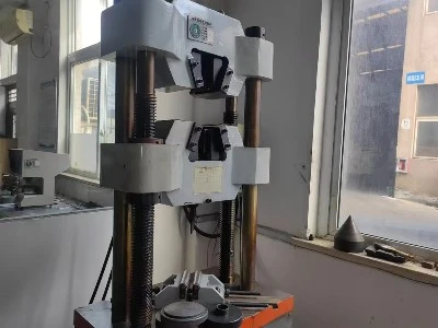
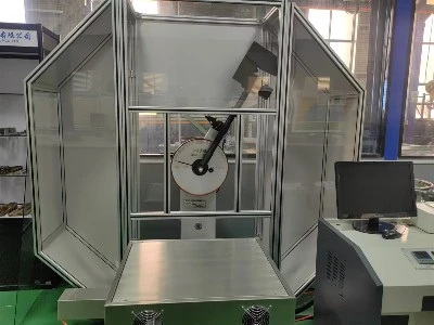
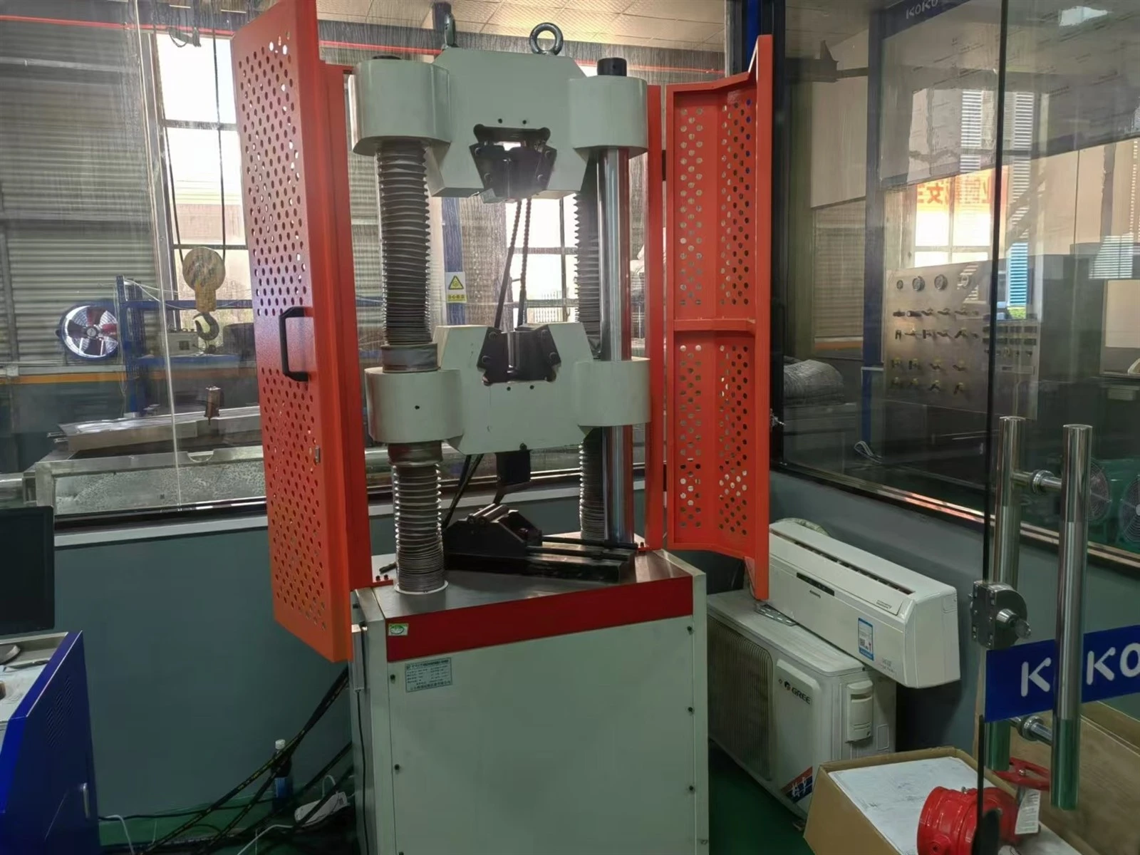
Each valve is subjected to pressure testing per the governing specification: shell test at 1.5 times the rated pressure and seat test at 1.1 times the rated pressure. Seat leakage for soft seats is accepted to ISO 5208 Rate A; testing is performed per API 598, ISO 5208, EN 12266-1 and API 6D as applicable.
Fire-safe design per API 607 / API 6FA / ISO 10497, with a metal-to-metal secondary seal and graphite fire seals so the valve retains shutoff after soft seats are exposed to fire.
Anti-static device per API 608: a spring or contact path keeps the ball, stem and body electrically continuous; the resistance is verified not to exceed 10 ohms.
Anti-blow-out one-piece ball and stem, retained by the top cover so the stem cannot be ejected by internal pressure.
Emergency sealant injection ports on the stem and seats (optional per API 6D) allow temporary sealing if a seat is damaged in service.
Cavity self-relief on SPE arrangements prevents over-pressurisation of the trapped body cavity.
Double block and bleed with a cavity bleed port, and DIB arrangements per the isolation requirement.
ISO 5211 actuator mounting pad and stem extension for buried or remote operation; ISO 15848 low-emission packing where specified.
Material traceability is documented by a Material Test Certificate to EN 10204 (3.1 as standard, 3.2 with third-party involvement on request), covering chemistry, mechanical properties, heat number and, where applicable, hardness and NACE compliance. Third-party inspection (for example SGS, BV, TUV) is supported when required by the contract.
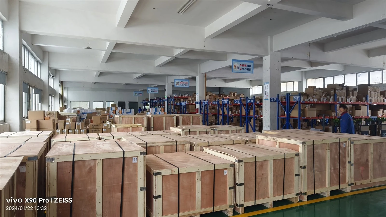
Packaging and shipping
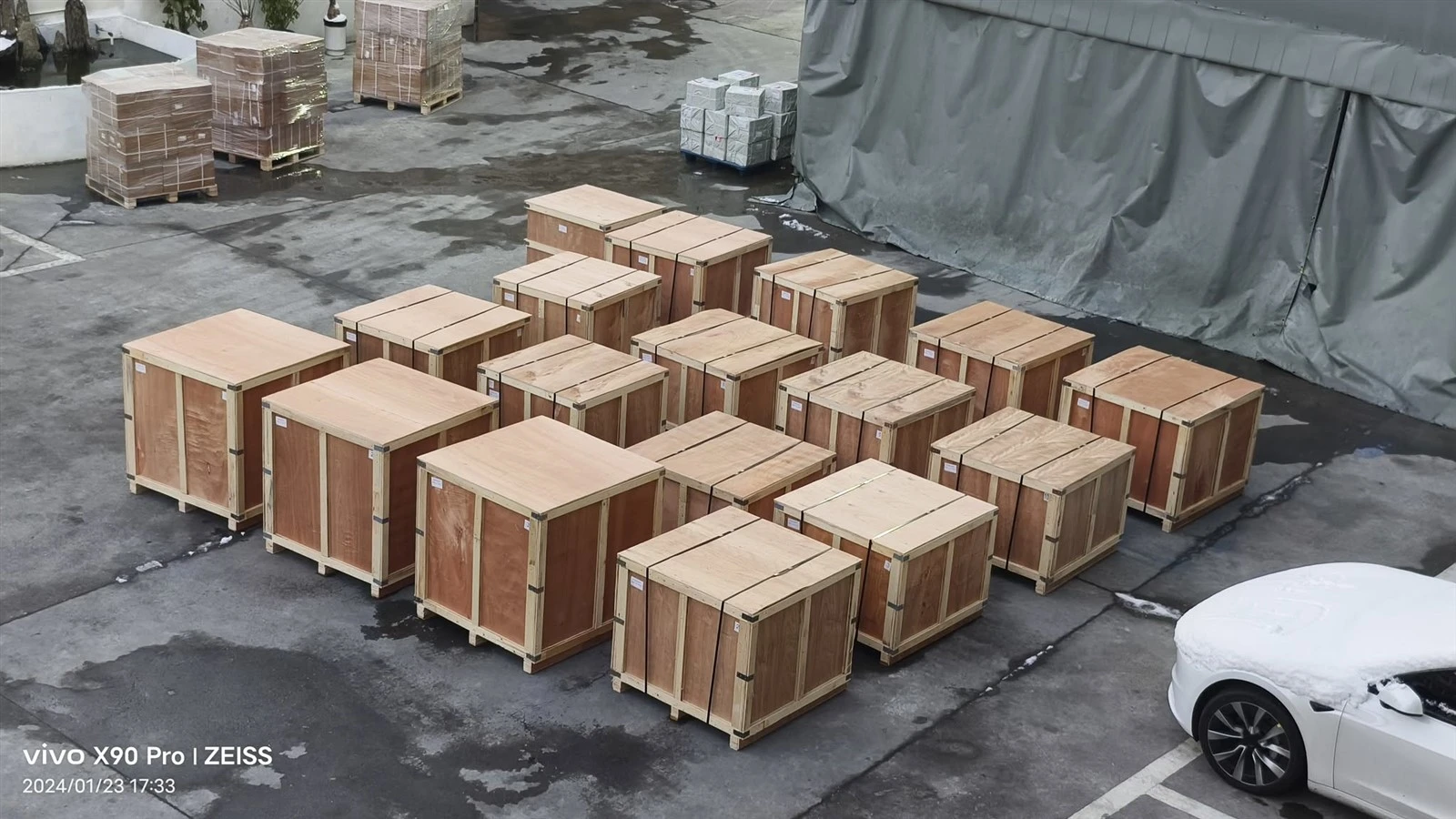
Provide the following to receive a quotation: nominal size and pressure class, body style and material (for example WCB or CF8M), end connection (flanged RF/RTJ or butt weld), seat material, bore type (full or reduced), applicable standard edition, DBB or DIB requirement with SPE/DPE arrangement, actuator type, whether the valve is for buried service with a stem extension, inspection and documentation requirements, and delivery destination with requested schedule. A data sheet or drawing helps confirm the specification.
Applications
Oil and gas transmission pipelines - mainline block valves, station and metering isolation
Buried and underground lines where top access through a stem extension avoids full excavation
Offshore and onshore production and export systems; subsea variants per API 6DSS where specified
Refinery and petrochemical high-integrity isolation and process gas or product lines
Tank farms, terminals and manifolds - pig launcher and receiver isolation
Space-restricted or congested skids where the valve cannot be removed for service
Suitability depends on design pressure, diameter, medium composition, temperature, corrosion control and the project specification. A top entry trunnion valve is selected where the fewest external joints, a compact body or in-place service through the top is decisive; the required seat arrangement and materials are confirmed against the purchase order.
FAQ
What is a top entry trunnion mounted soft seated ball valve?
It is a quarter-turn isolation valve built from a single (one-piece) body with a bolted top cover, in which the ball is fixed by top and bottom trunnions and sealed by spring-loaded soft seats. Because the internals are installed and removed through the top, the ball, trunnions and seats can be serviced without taking the body out of the pipeline.
How is a top entry valve serviced without removing it from the pipeline?
The body stays connected to the line while the top cover is unbolted and lifted off, exposing the ball, trunnion assemblies and seat cartridges, which are then removed through the top opening. The pipe run is not cut, drained or re-aligned, so maintenance can be carried out in place, which also makes the design suitable for buried or space-restricted installations. Dedicated tooling is normally used for the service work.
What is the difference between a top entry and a two-piece or three-piece ball valve?
A two-piece or three-piece valve is split along the ball centerline or into end caps plus a centre section, so it carries one or two bolted body joints on the outside of the valve. A top entry valve keeps a single uninterrupted body and places the only main bolted joint on the top cover, giving the fewest external joints and the fewest potential leak paths, at the cost of needing the top cover opened for any internal service.
What size and pressure range does a top entry trunnion ball valve cover?
Typical supply is NPS 2 to 48 (DN50 to DN1200) and Class 150 to 2500 (PN10 to PN420), in full bore or reduced bore, with flanged (RF/RTJ) or butt-weld ends. Larger bores and higher pressure classes are evaluated per inquiry. The single-body top entry design is often selected for large-diameter transmission and buried service, where its compact face-to-face and top access are advantageous.
What body and trim materials are available, and can it be supplied for sour or low-temperature service?
Cast bodies are typically ASTM A216 WCB or WCC carbon steel, ASTM A352 LCB or LCC for low temperature, and ASTM A351 CF8, CF8M, CF3 or CF3M stainless steel; forged bodies are A105 or A350 LF2 and A182 F304 or F316. The ball and trunnion shafts are commonly A182 F304 or F316, 17-4PH or 13Cr, with optional hard-facing. Sour-service valves can be supplied to NACE MR0175 / ISO 15156 and low-temperature valves to A352 LCB/LCC or A350 LF2, subject to confirmed service conditions.
What soft seat materials are used and what leakage rating applies?
Common soft seats are PTFE (about -29 to +200 degC), RPTFE reinforced with glass or carbon (about -29 to +230 degC), PEEK (about -20 to +260 degC), Nylon (about -20 to +120 degC) and Devlon nylon composite (about -20 to +220 degC); the usable window also depends on pressure and medium. Soft seats are tested for seat leakage to ISO 5208 Rate A (bubble-tight); a metal-seat backup, where fitted for fire or elevated temperature, is evaluated to ISO 5208 Rate D.
What seat arrangements are available - DBB, DIB, SPE, DPE?
With two independently loaded seats the valve provides double block and bleed (DBB) or double isolation and bleed (DIB). DIB-1 uses double-piston-effect seats on both sides (DPE x DPE); DIB-2 uses a single-piston-effect upstream seat and a double-piston-effect downstream seat (SPE x DPE). SPE seats self-relieve cavity pressure to the low-pressure side, while DPE seats seal against pressure from either direction. The required arrangement follows the project isolation philosophy.
What information is needed to request a quotation?
Provide the nominal size and pressure class, body style and material (for example WCB or CF8M), end connection (flanged RF/RTJ or butt weld), seat material, bore type (full or reduced), applicable standard edition, DBB or DIB requirement with SPE/DPE arrangement, actuator type, whether the valve is for buried service with a stem extension, inspection and documentation needs, and delivery destination with schedule. A data sheet or drawing helps confirm the specification.
Hot Tags: top entry trunnion mounted soft seated ball valve, China top entry trunnion mounted soft seated ball valve manufacturers, suppliers, factory, api 6d floating ball valves, API 6D Trunnion Mounted Ball Valves, ball valve compliance, ball valve full turn valves, ball valve logistics, ball valve stock